Wiring Diagram Usb Plug Wiring Digital and Schematic
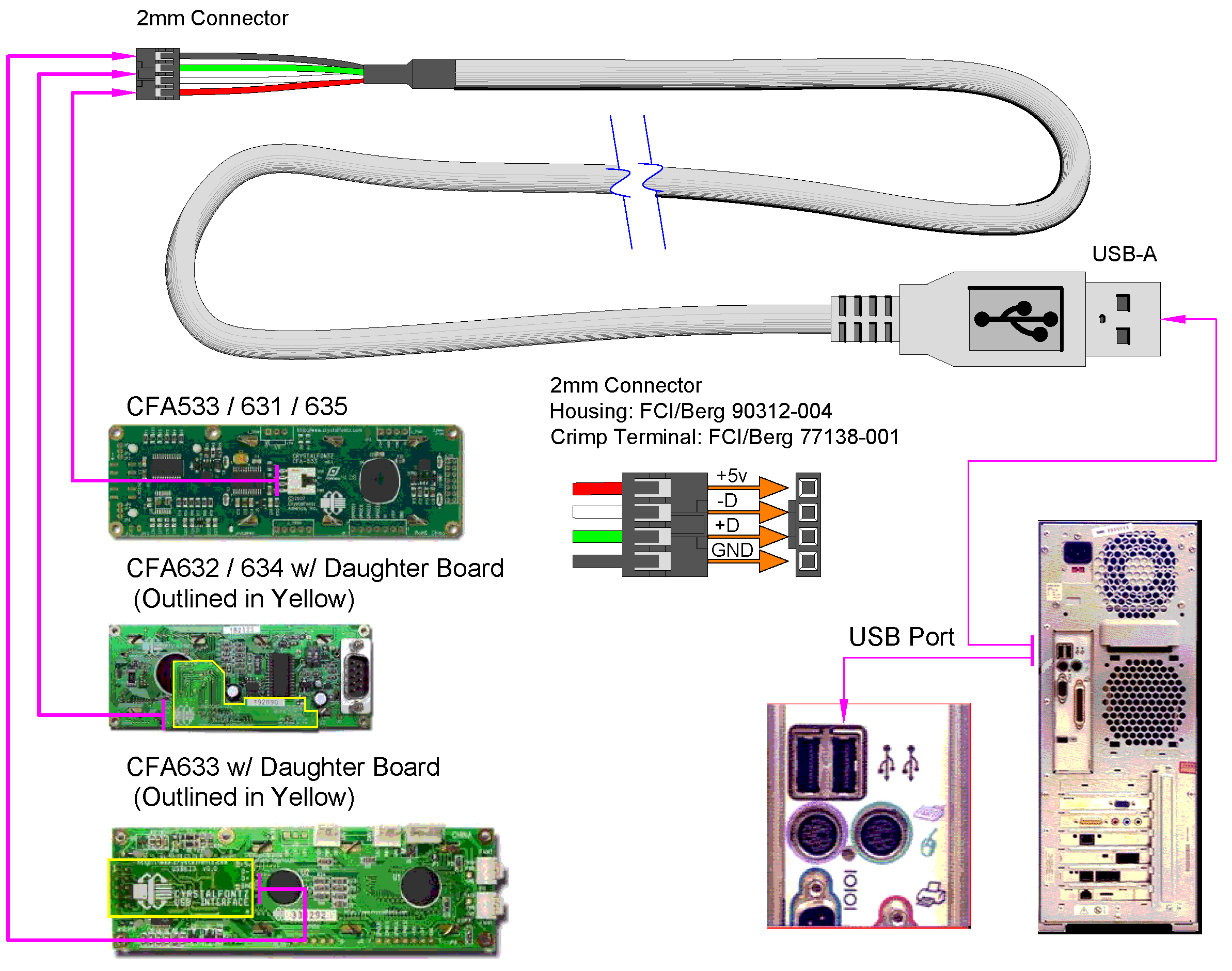
USB Pinout Diagram. A USB cable's wiring and connections can be visualized with the help of a pinout diagram. Type-A, Type-B, Mini-USB, Micro-USB, and USB-C are just a few of the varieties of USB connectors available. Pinout diagrams, which display the configuration and functionality of connectors, are specific to each variety. USB Pinout: Type-A

⭐ Micro Usb Cable Wiring Diagram To Rs232 ⭐ Noir souvenier
These micro USB C cables are available in different assemblies in different USB versions for various purposes, from USB C charging/ data cable to USB C OTG cable. You can check USB C wiring diagrams and internal wirings of USB 3.0/ 3.1. The image and pinout of USB b super speed are as follows:

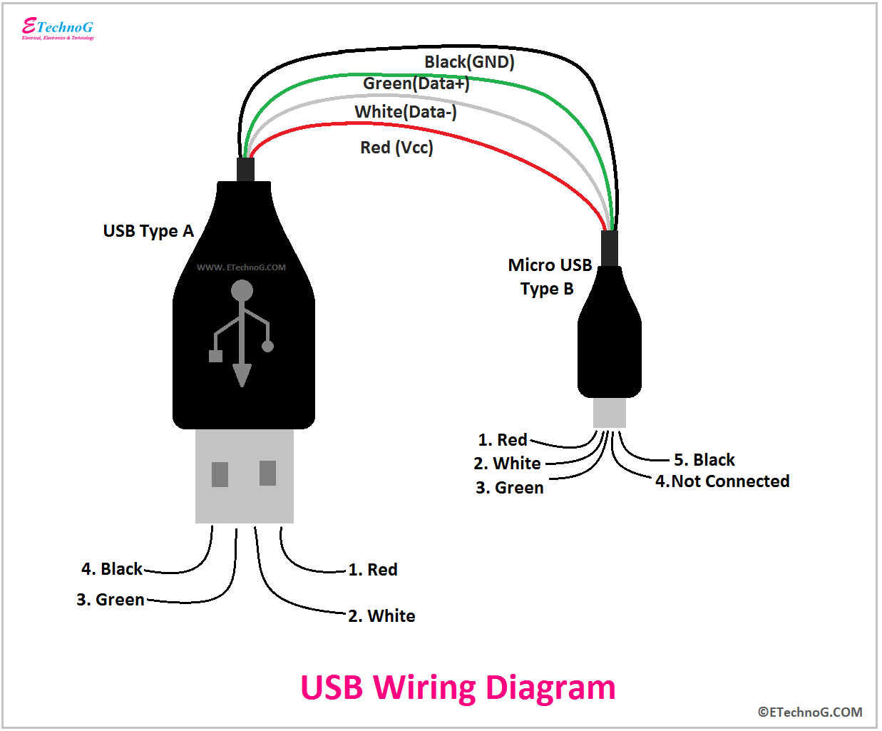
Micro Usb Cable Wiring Diagram Extension Different Wire Color Data Usb Cable Usb Cable
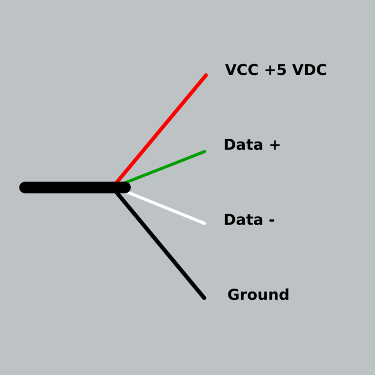
It also shows the arrangement of wires in a USB cable clearly. Source: somanytech.com USB Type-A connector Diagram To show each wire clearly and in detail, you can create this USB wiring diagram. Using appropriate colors, the diagram labels all the wires in a USB cable and then informs what each color stands for.

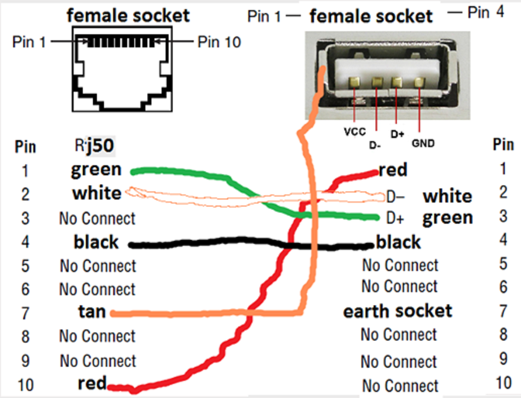
RC USB over Cat6
USB C cable wiring diagram This article mainly introduces the USB C cable wiring diagram, the pin definition of the 24P in USB Type C interface and how to connect the core wires, as a reference for hardware design Let's first understand the pin definition of 24Pin USB C Female Male For the USB C cable, we mainly introduce the male connector It can be clearly seen that the Pin position of the.
micro usb wiring colors Wiring Diagram
The USB pinout can be divided into two parts: USB Connector Pinout and USB port Pinout.. Know the Difference(Speed, Cable length) USB Mini A and Mini B. USB Mini was the first improvised version of the normal connectors. This version was launched for both Type A and Type B.. The pinout diagrams of the superspeed versions of different USB.

Usb To Mini Usb Wiring Diagram, Ide To Usb Wiring Schematic Wiring Diagram
USB wiring diagrams typically include information about the different pin numbers, wire colors, and functions of each wire. For example, in a USB Type-A connector, pin 1 is usually the +5V power supply, pin 2 is the Data- signal, pin 3 is the Data+ signal, and pin 4 is the ground.. A typical USB cable wiring diagram follows the following.